This post continues my blog series “Building a Telco Test Lab Using srsRAN”. In the previous chapters I covered CPU isolation, TuneD, DPDK, NIC optimization, and PTP. With all of that in place, we can finally start deploying our first RAN.
To keep things structured, I split this topic into two parts. Part 1 focuses on verifying the DU and RU setup before attaching any UE. Part 2 will cover attaching an off-the-shelf COTS UE.
A complete end-to-end RAN involves many moving parts and a lot of configuration options that can go wrong. To avoid unnecessary issues during the initial UE attach, I always verify the system using a fuction of the srsRAN gNB called testmode. It exercies the whole stack and helps me check if the server is capable of running the desired configuration before bringing a real UE into the picture.
The RU
The Radio Unit (RU) is usually one of the most expensive components in a Split 7.2 deployment. If you don’t have access to an RU, there are alternatives worth mentioning.
At SRS we developed a small tool called the RU Emulator. As the name suggests, it emulates an RU. You can run it on another machine and connect it to your DU server. It helps exercise the entire network path and can reveal potential issues during debugging. It also exposes OFH KPIs such as late and early packets. You can find it in the OFH examples in the srsRAN Project repo.
Another interesting project is ProtO-RU. It adds low-PHY and UHD support to the RU Emulator and turns a USRP into a Split 7.2 RU. I haven’t had a chance to try it myself, but it looks like a very cool option if you want to experiment without purchasing an actual RU. You can find it on the GitHub page: https://github.com/NUS-CIR/ProtO-RU.
What testmode Is
testmode is a feature inside the srsRAN gNB that simulates one or more UEs connected to the network. It can be used with or without an RU. Using it with a real RU also exercises the OFH layer, providing a realistic picture of how the network performs with the same number of actual UEs attached.
It helps verify the DU and RU configuration by confirming:
- The PTP configuration is correct
- The DU and RU settings match
- The system has sufficient performance for the selected configuration
- The deployment can handle a certain number of UEs transmitting or receiving traffic
Attaching a real UE requires every component of the network to work and be configured correctly. testmode helps rule out most configuration issues before attempting a UE attach.
Build the gNB
As the firs tep I build the gNB. Use the following commands:
git clone https://github.com/srsRAN/srsRAN_Project.git
cd srsRAN_Project
mkdir build
cd build
cmake ../
make test -j $(nproc) gnb
Prepare the Configuration Files
Before running testmode you need configurations for both the RU and the gNB. As a first step I recommend starting with the srsRAN example configuration files and adjusting them to match the RU. Here is an example setup I often use:
- BFP9 compression
- Dynamic header compression UL/DL
- TDD 7D2U
- 100 MHz
- Single cell
The main sections of the config file you’ll adjust are: cu_cp, ru_ofh, and cell_cfg. I’ll walk through the basics of each.
All configuration parameters of the gNB are available via the --help function. It uses submenus. For example, to inspect the OFH settings:
gnb ru_ofh --helpAnother good reference is the srsRAN Configuration Reference.
cu_cp
In this section we define the CU configuration. Example:
cu_cp:
  amf:
    addr: 127.0.0.5
    port: 38412
    bind_addr: 127.0.0.100
    supported_tracking_areas:
      - tac: 7
        plmn_list:
          - plmn: "00101"
            tai_slice_support_list:
              - sst: 1
The addr field sets the IP of the AMF. bind_addr defines the DU interface connected to the core. Make sure the bind_addr IP is available and that you can ping the AMF and UPF. In this example I am using localhost for both addresses because Open5GS will be installed on localhost in the next blog post. You can also configure an external IP if you want to reach a core on an external machine.
ru_ofh
In this section we define the OFH parameters. Example:
ru_ofh:
  t1a_max_cp_dl: 535
  t1a_min_cp_dl: 286
  t1a_max_cp_ul: 535
  t1a_min_cp_ul: 286
  t1a_max_up: 390
  t1a_min_up: 80
  ta4_max: 500
  ta4_min: 25
  is_prach_cp_enabled: true
  compr_method_ul: bfp
  compr_bitwidth_ul: 9
  compr_method_dl: bfp
  compr_bitwidth_dl: 9
  compr_method_prach: bfp
  compr_bitwidth_prach: 9
  enable_ul_static_compr_hdr: false
  enable_dl_static_compr_hdr: false
  ru_reference_level_dBFS: -24
  subcarrier_rms_backoff_dB: auto
  cells:
    - network_interface: 0000:01:01.0
      ru_mac_addr: 70:b3:d5:e1:5b:06
      du_mac_addr: 00:33:22:33:00:11
      vlan_tag_cp: 5
      vlan_tag_up: 5
      prach_port_id: [4, 5]
      dl_port_id: [0, 1, 2, 3]
      ul_port_id: [0, 1]
At the top I set the PTP timing window parameters (t1a_* and ta4_*). These are the defaults and should work with most RUs. Some RU vendors provide recommended values, check the documentation.
If you see small amounts of late/early packets, follow these steps to adjust the timing window. Adjust only one plane at a time:
- Run testmode traffic for ~30s
- Record the average late/early packet rate
- Adjust the timing window:
- Late packets → increase min/max equally
- Early packets → decrease min/max equally
- Apply changes and rerun the test
You can increase the window size instead of shifting it, but this cannot be increased indefinitely.
After that I define the compression settings. Here I define BFP9 and dynamic header compression.
Next, the IQ scaling settings using subcarrier_rms_backoff_dB and ru_reference_level_dBFS. Your RU vendor should be able to give you the values for the subcarrier RMS backoff.
The last section, cells, defines per-cell configuration, including MAC addresses, interface name, VLANs, and PRACH/UL/DL port IDs. In this example I use a 4×2 antenna configuration.
The cells section stores the section that are important for the DU. In case The cells section contains the parameters relevant for the DU.
If you use DPDK, set network_interface to the BDF of the PF or VF that is bound to a DPDK driver.
Quick explanation of the remaining parameters:
- du_mac_addr: MAC address of the DU interface toward the RU
- ru_mac_addr: MAC address of the RU interface toward the DU
- vlan_tag_{ul,dl}: VLAN tags for UL and DL (comment out to disable)
- prach_port_id: PRACH port mapping
- {ul,dl}_port_id: UL/DL port mappings on the RU
All of these parameters must match the corresponding values defined in the cell_cfg section.
cell_cfg
This section defines global settings for all cells:
cell_cfg:
  dl_arfcn: 637212
  band: 78
  channel_bandwidth_MHz: 100
  common_scs: 30
  plmn: "00101"
  tac: 7
  pci: 1
  nof_antennas_dl: 4
  nof_antennas_ul: 2
  prach:
    prach_config_index: 159
    prach_root_sequence_index: 1
    zero_correlation_zone: 0
  ssb:
    ssb_block_power_dbm: -11
  tdd_ul_dl_cfg:
    dl_ul_tx_period: 10
    nof_dl_slots: 7
    nof_dl_symbols: 6
    nof_ul_slots: 2
    nof_ul_symbols: 4
First I define the EARFCN, band, bandwidth, and SCS. PLMN and TAC must match what you configured in the cu_cp section. The antenna parameters must match the port IDs in ru_ofh.
For this post I use short PRACH (config index 159).
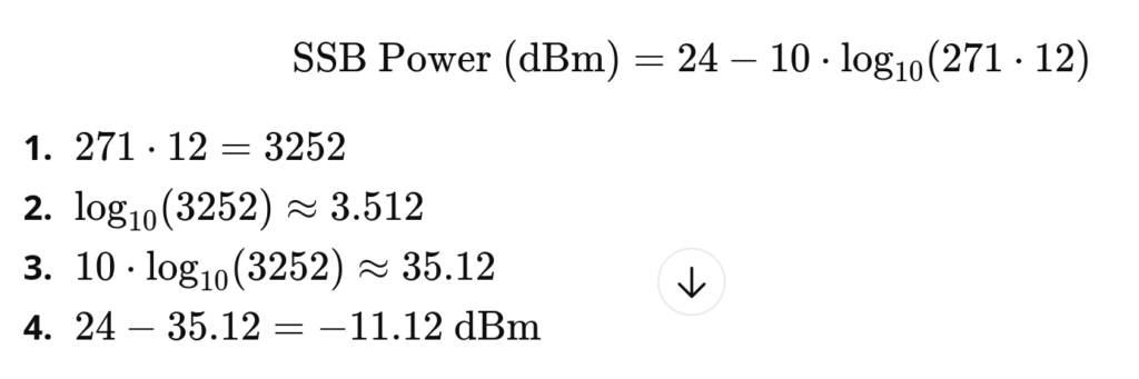
The SSB block power (ssb_block_power_dbm) depends on the RU’s reference power and the number of PRBs. I use the following formula:

For 100 MHz / 30 kHz SCS you get 271 PRBs. With an RU reference power of 24 dBm, an SSB block power value of -11 dBm is appropriate in this example.
It is essential that all of the above settings match the configuration inside your DU and RU. Refer to your vendor’s documentation for the correct procedure of configuring the RU.
In the next blog post I will show how to adjust the DU parameters for proper UE path loss calculations and optimal throughput.
hal
This section defines the eal_args for DPDK.
hal:
  eal_args: "--lcores (0-1)@(1-11,13-23)"
This means:
- Defines DPDK lcores (DPDK worker threads) 0 and 1
- Run lcores on the CPU set 1-11, 13-23 (isolated CPU cores)
Setting these settings is required to enable DPDK in the gNB. You have to comment them out if you are not using DPDK.
testmode
This section defines the Testmode options.
test_mode:
  test_ue:
    rnti: 0x44
    ri: 4
    cqi: 15
    nof_ues: 1
rnti
- RNTI assigned to the simulated UE
- For multiple UEs, the RNTI will increment starting from this value
ri
- Rank Indicator
- Supported values: up to RI=4 in DL and RI=1 in UL
cqi
- CQI value used for the simulated UE
nof_ues
- Number of simulated UEs to create
Below is an example configuration with all adjustments applied. In this example I also enabled DPDK.
Validate RU and PTP
Before running testmode, check that the RU is operating correctly. Make sure it has locked PTP and is ready to accept traffic. This process depends heavily on your RU model.
Also ensure that the PTP configuration from Chapter 5 has been applied correctly. Double-check that ptp4l and phc2sys are running and stable.
Run gNB in testmode
Running the srsRAN gNB is straight forward:
sudo ./build/apps/gnb/gnb -c ~/srsran-gnb.yamlThe gNB is now running testmode as you can see in the console metrics. The goal now is to verify:
- Logs are free of warnings and errors
- CPU load still has headroom for traffic spikes
- No obvious RF or timing issues under load
If the gNB didnt start use the Config Reference or --help function to solve the issue.
To narrow down potential issues, I follow these steps:
- Inspect stdout for potential problems (BLER, NOKs, etc.)
- If output looks problematic → check
htopand the logs- htop for performance issues
- logs for gNB related warnings/errors
- Narrow down errors and warnings:
- Misconfiguration indicators:
- Missed sending in slot X
- Missed slot
- Received packet in wrong slot
- Performance issue indicators:
- Woke up late
- DL queue is full
- Timeout reached
- Real-time failure
- Misconfiguration indicators:
Debugging the RU, DU, or PTP in detail is out of scope for this post. I’ll cover this in a future series. From experience, over 90% of errors stem from misconfigurations between DU and RU. If you see errors, the best approach is to verify your configuration thoroughly and ensure DU and RU settings match.
Optional: Verify with a Spectrum Analyzer
Once the log file is clean, I usually check with a spectrum analyzer that the RU is transmitting in the correct band and frequency, and that the output power is sufficient for UE attach.
You don’t need expensive equipment here. A simple spectrum analyzer built from a USRP is enough. You just need to confirm that the RU is transmitting and at a reasonable power level.
Summary
In this chapter we looked at how to configure the gNB and match it to the RU settings. We also validated the deployment using testmode to ensure the configuration is correct and that the system has enough performance for the selected setup.
In the next chapter I will show how to set up the core network and attach a real UE. I’ll also give a quick introduction to the power-calibration step once the UE is connected.