This chapter walks through how to deploy a complete RAN setup on a Kubernetes cluster using the srsRAN gNB together with Open5GS as the core network. I am using a single-node cluster on the machine I optimized in earlier chapters. I assume that all earlier chapters have been completed successfully, because I rely on the configuration and files created there.
srsRAN Helm Charts
In this post I use Helm charts to deploy workloads on a Kubernetes cluster. Make sure you have access to your cluster and Helm installed and working.
For the most recent updates clone the srsRAN Helm chart repository directly from GitHub:
git clone https://github.com/srsran/srsRAN_Project_helmk9s
k9s is a terminal UI for Kubernetes that helps me a lot with quick debugging and navigating logs. Install instructions: https://k9scli.io/topics/install/
Preparing the Kubernetes Cluster
As a first step, I show how I set up Kubernetes nodes for real-time workloads such as the srsRAN gNB. I assume you already have a Kubernetes cluster (v1.26 or higher) and a basic understanding of the environment.
Configure the CPU Manager (Static Policy)
For real-time workloads like the srsRAN gNB, it is important that the scheduler places Pods only on isolated CPU cores to avoid jitter. To achieve this, I configure the kubelet to use the static CPU Manager policy.
With this configuration, all Pods running with the Guaranteed QoS class are placed on isolated CPU cores. In order for the scheduler to distinguish between isolated cores and housekeeping cores, we must explicitly define which CPUs are reserved for system tasks.
In this example, I reserve cores 0 and 12 for the system. Core 0 is the physical core, and core 12 is its corresponding hyperthreading sibling. I also enable full-pcpus-only because I do not want the gNB to share CPU resources with any other process. This option ensures that physical CPU cores are always allocated together with their hyperthreading siblings.
The downside of enabling this option is that only an even number of CPU cores can be allocated to Pods running with the Guaranteed QoS class on this system.
If hyperthreading is disabled, I sometimes run into issues when reserving a single CPU using reservedSystemCPUs. As a workaround, I specify the same core twice, for example reservedSystemCPUs: 0,0.
An example kubelet configuration enabling the static CPU manager:
cpuManagerPolicy: static
reservedSystemCPUs: 0,12
featureGates:
  CPUManagerPolicyOptions: true
cpuManagerPolicyOptions:
  full-pcpus-only: "true"
What these parameters do
cpuManagerPolicy: static
Enables the static CPU Manager policy. QoS Guaranteed pods receive full, isolated CPU cores.
reservedSystemCPUs: 0,12
These cores are reserved for system tasks only. No pods run there.
featureGates
Required to enable the CPU manager functions likefull-pcpus-only.
full-pcpus-only: "true"
Forces Kubernetes to assign full physical CPUs including hyperthreading siblings if enabled.
How to update the kubelet config
- Drain the node
kubectl drain <node> --ignore-daemonsets- Remove the CPU Manager state file
sudo rm -rf /var/lib/kubelet/cpu_manager_state- Edit the kubelet config
Add the CPU manager snippet to the bottom of:
/etc/kubernetes/kubelet-config.yaml- Restart kubelet
sudo systemctl restart kubelet- Uncordon the node
kubectl uncordon <node>(Optional) SR-IOV Network Device Plugin
If you don’t want to give gNB pods full root access to network devices on the host, you can use the SR-IOV Network Device Plugin.
This plugin enables you to allocate Virtual Functions (VFs) or physical interfaces on the fly. This way you dont have to grant privileged access to the host. The srsRAN Helm chart supports dynamically updating the gNB config file to use the dynamically allocated network interfaces.
In the following section I will show how to configure a VF of a E810 bound to vfio-pci.
Configuration
All configuration files are packed here:
You can also find all of these files on the official Github repo.
The SR-IOV plugin creates device plugin endpoints based on the configMap.yaml definition. You need to specify the vendor and device ID.
Example VF:
lspci -nn -s 01:01.0
01:01.0 Ethernet controller [0200]: Intel Corporation Ethernet Adaptive Virtual Function [8086:1889] (rev 02)
Vendor = 8086
Device = 1889
Create the ConfigMap:
apiVersion: v1
kind: ConfigMap
metadata:
  name: sriovdp-config
  namespace: kube-system
data:
  config.json: |
    {
      "resourceList": [
        {
          "resourceName": "intel_sriov_dpdk",
          "resourcePrefix": "intel.com",
          "selectors": [
            {
              "vendors": ["8086"],
              "devices": ["1889"],
              "drivers": ["vfio-pci"],
              "needVhostNet": true
            }
          ]
        }
      ]
    }
This groups all Intel E810 VFs that are bound to vfio_pci into the resource intel.com/intel_sriov_dpdk. If you have used a different driver in Chapter 3 you want to use that driver here.
The SRIOV DaemonSets can be restricted using nodeAffinity if needed. In my example configs, they are pinned to nodes with hostname srskit1. Remove the affinity if you are using a single node cluster or adjust it to your node’s name.
Deployment
Multus is required for the SR-IOV provider to work. I’ve included a manifest for it in the example config package, which you can apply directly. If you prefer using a newer release, check the SR-IOV project’s GitHub page for the latest installation instructions.
kubectl apply -f multus-daemonset-thick.ymlAfter that we can deploy the remaining manifests for the SRIOV provider.
kubectl apply -f configMap.yaml
kubectl apply -f sriov-cni-daemonset.yaml
kubectl apply -f sriov-crd.yaml
kubectl apply -f sriovdp-daemonset.yaml
Infrastructure Pods (TuneD & LinuxPTP)
At SRS we created two Helm charts that help manage system-level configuration as code. They are inspired by the OpenShift linuxptp and tuned operators but designed to work on any Kubernetes cluster without requiring OpenShift. These charts make it possible to version-control system tuning and time-sync settings and redeploy them reliably. If a node fails, you can reapply the same charts and restore most of your environment once its replaced.
Below I show how I use the configuration from earlier chapters (TuneD from Chapter 1 and LinuxPTP from Chapter 5).
TuneD
The TuneD Helm chart deploys a TuneD profile onto the node and restarts the TuneD service automatically when the profile content changes.
For the configuration of the TuneD chart, I copy the profile I created in Chapter 1 and place it under the profileContent section inside the chart’s values.yaml. Make sure to overwrite the example configuration with your own.
Important parameters
hostPathTuned
Path on the host where TuneD profiles live.securityContext
Must be set toprivilegedso the Helm chart can restart the server.restartOnConfigChange
If enabled, nodes reboot when the profile changes.reboot
Defines how and when the reboot is executed.
Example deployment command
helm install tuned-srskit1 ./ -n infra -f ./values.yaml --create-namespace(Replace ./ with the folder of the TuneD chart from the cloned srsRAN Helm repo.)
LinuxPTP
The LinuxPTP Helm chart deploys ptp4l, phc2sys, and optionally ts2phc inside Kubernetes instead of running them directly on the host. This allows you to keep all timing-related configuration in a Git-driven IaC workflow. The chart also includes liveness/readiness probes that check PTP health by parsing logs in real time.
I reuse the same configuration I created in Chapter 5. From the example config provided in the values.yaml of the chart, I remove everything I don’t use and set:
ts2phc:
  enabled: false
Key chart features explained
ntp
Optionally resets the NIC and the system’s PHC to NTP time on container restart (helpful for LLS-C1 without GPS).- Probes (
liveness,readiness,startup)
Validate Pod health automatically by monitoring logs. interfaceNameList
Allows defining multiple interfaces for multi-cell LLS-C1 setups, or a single interface otherwise.securityContext
Must run privileged due to PHC access requirements.config
Yourptp4landphc2sysconfiguration copied from Chapter 5.
Example deployment command
helm install linuxptp-srskit1 ./ -n infra -f ./values.yaml --create-namespaceRT Tests
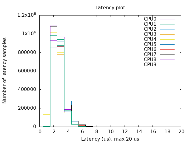
To verify a deployment, we at SRS have created a Helm chart that runs cyclictest together with stress-ng.
cyclictest measures thread wake-up latency and gives a clear indication of how deterministic the system behaves under load. The maximum latency a node can tolerate depends on the SCS used in the deployment:
- 60 kHz SCS → ~17.8 µs per symbol
- 15 kHz SCS → ~71.4 µs per symbol
- 30 kHz SCS → ~35.7 µs per symbol
For cyclictest, the important thing is that the maximum measured wake-up time stays below the symbol duration for the SCS you are using.
Configuration
You can use the default values file included in the RT Tests chart. Adjust the values according to your CPU configuration. Below is a short explanation of the defaults:
config:
  rt_tests.yml: |-
    stress-ng: "--cpu 16 --iomix 4 --vm 2 --vm-bytes 128M --fork 4 --timeout 12h"
    cyclictest: "--mlockall --priority 95 --distance 0 --threads 16 --histogram 25 --quiet --duration 12h"
Explanation of the parameters
stress-ng:
--cpu 16runs 16 CPU stress workers--iomix 4adds mixed I/O load--vm 2 --vm-bytes 128Mcreates two memory-stress workers allocating 128 MB each--fork 4stresses process creation--timeout 12hkeeps the stress load running for 12 hours
cyclictest:
--mlockalllocks memory to avoid page faults--priority 95assigns a high RT priority to the threads--distance 0wakes all threads at the same time--threads 16launches 16 test threads--histogram 25collects latency histogram data--quietsuppresses detailed output--duration 12hruns cyclictest for 12 hours
Running the test
Deploy the chart using:
helm install rt-test ./ -f values.yamlThe test results will be written to the output directory you configured (default: /var/lib/rt-tests). Inside that directory, you will find a diagram similar to the one shown in this post, summarizing the wake-up latency distribution.
Example configs for all 3 chats:
Summary
In this chapter we prepared the Kubernetes environment for running real-time RAN workloads. We cloned the srsRAN Helm repository, set up the tuning and timing infrastructure using TuneD and LinuxPTP Helm charts, and created a repeatable IaC setup. These components ensure that every node in the cluster runs with consistent CPU isolation, PTP timing, and system tuning, all are critical for stable srsRAN gNB performance.
In the next chapter, I’ll continue by deploying the srsRAN gNB and integrating Open5GS using Helm. At the end of the next post you will have your whole RAN running inside of K8s! Stay tuned!